Track Geometry
Background
The measurement of track geometry parameters is of critical important for railways. Poor track geometry can lead to excessive rail and wheel wear, abnormal track loading and acceleration issues, broken rail and fastenings and train derailment. All measurements are thresholded to find exceptions and clustered to show the start and end of track positions where track geometry is abnormal.
Rails wear over time and may sustain damage in the form of squats, wheelburns, shelling, corrugation, head-checks and eventually rail breakage. Several factors may be responsible including poor rail-wheel interaction, excessive track load, poor track geometry, damage caused by flat wheels, internal manufacturing defects, missing or loose fastenings in joint areas, poor rail grinding and so on. Once the top hard surface starts to wear out, rail surface wear can quickly spread; if rails experience repeated abnormal loads on weak spots, internal breakages quickly gain momentum and lead to rail fracture. The rail may suffer damage from top, side or in web areas. Figure 1 below shows an example of how poor rail wheel interaction causes corrugation, figure 2 shows a variety of rail defects that can develop over time, Figure 3 shows specific examples of visible rail defects on the surface based on internal damage.
Gauge Measurement
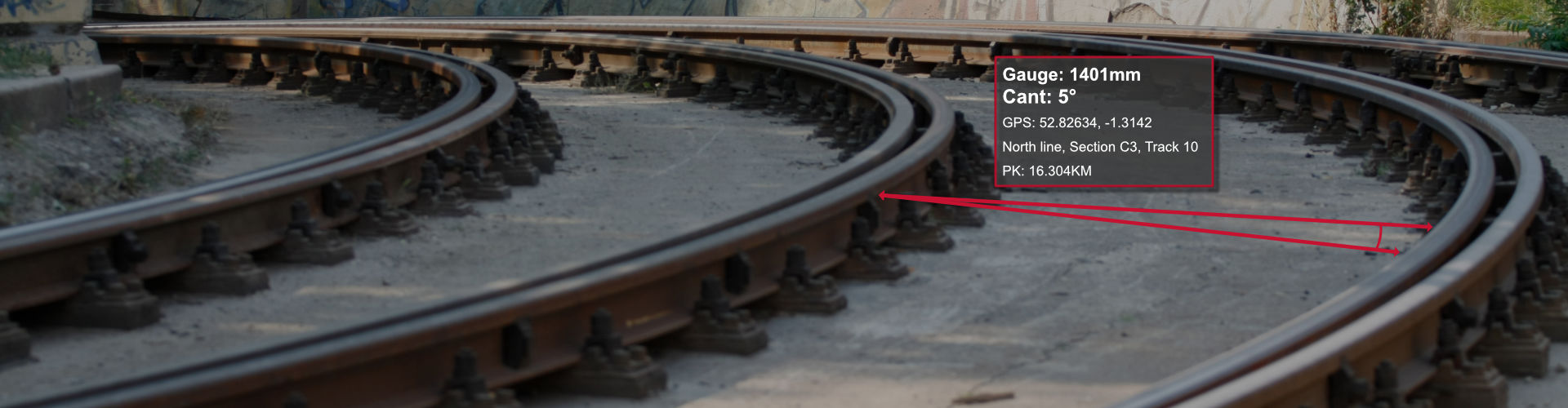
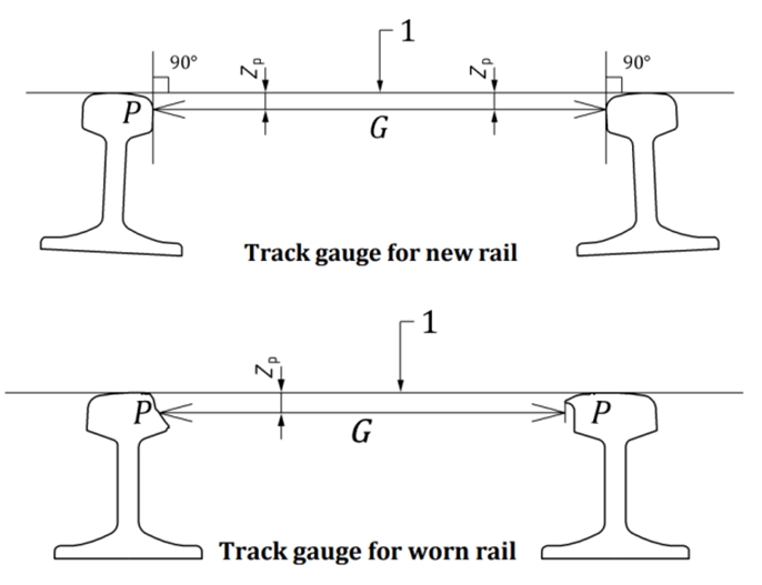
Track gauge or rail gauge (also known as track gauge is the distance between the inner sides (gauge sides) of the heads of the two load bearing rails that make up a single railway line. Each country uses different gauges for different types of trains. However, the 1,435 mm (4 ft 8+1⁄2 in) gauge is the basis of 60% of the world’s railways. Wide gauge is a major cause of train derailments. Any rail movement towards the field side widens the gauge which must be consistently monitored. The inspection of gauge around curves is particularly important and usually it should be measured every 25-50cm along the track. The main difference between using portable instruments to measure it compared to
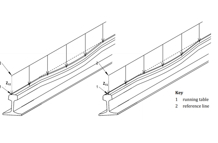
Longitudinal Twist Measurement
Track twist is the difference of the track cant between one point of measurement and another point along the track. The distance between the two points is fixed during the measurement and is called the base of the twist. If the base is 3 m then the measured twist is called 3 m twist.
Twist faults may be created as a result of uneven settlement of track, voids below the sleeper due to them being packed incorrectly or ballast being washed away, poor drainage, poor foundations etc.
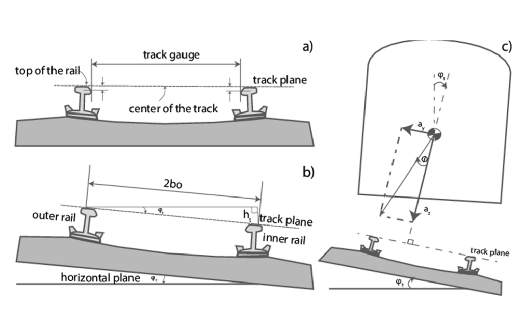
Cant Measurement
The cant of a railway track or camber of a road (also referred to as superelevation, cross slope or cross fall) is the rate of change in elevation (height) between the two rails or edges. Accurate rail cant measurements can help identify potential problems at the rail / crosstie interface, such as rail seat abrasion, ineffective fasteners, plate cutting, missing or worn crosstie pads, and rail base / tie plate misalignment. Deficiency is what the passenger actually feels; the bumps and jolts the train makes due to the track. Excessive cant can be a threat to the vehicle at high speeds on curves where large lateral forces can derail the vehicle.
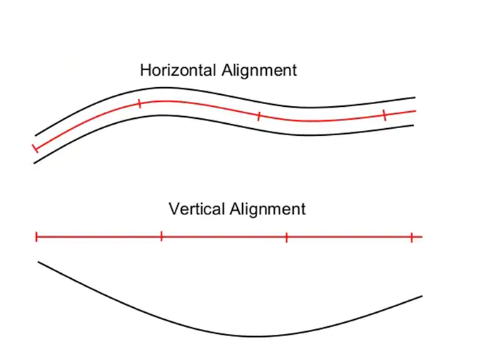
Alignment Measurement
The term alignment describes the line uniformity (straightness) of the rails. The horizontal alignment is done by using a predefined length of string line to measure along the gauge side of the reference rail. It is the distance (in inches or millimeters) from the midpoint of the string line to the gauge of the reference rail. The design horizontal alignment for tangent track is zero (perfect straight line on the horizontal layout).
The vertical alignment is the surface uniformity in the vertical plane. The measurement of uniformity is done using a predefined length of string line (normally the same length used in horizontal alignment) along the track. If the midpoint of the measurement has higher elevation, it is called hump deviation. On the other hand, if the midpoint has lower elevation, it is called dip deviation.
RV Diagnostics
TrackVue Z series equipment is used to make Track geometry measurements using contactless technology.
Laser systems combined with inertial sensors make a number of geometry measurements at high speeds every 20 cm along the direction of movement as shown below. The system is designed to work in any outdoor condition and for any track gauge. The system may be customised to meet formatting requirements for customers and may be adapted to report on measurements as set out by US, European and Asian standards. The following table shows the measurements made.
| Track Geometry Measurements | |
|---|---|
| Rail | Type, track position |
| Cant | Cant and cant deficiency in mm, track position |
| Twist | Twist in mm over a set distance say 5m, track position |
| Curvature | Radius in mm, track position |
| Gauge | Gauge in mm measure 14mm below rail level, track position |
| Vertical alignment | Alignment in mm, filtered versions available |
| Horizontal alignment | Alignment in mm based on selected chord length, filtered versions available |
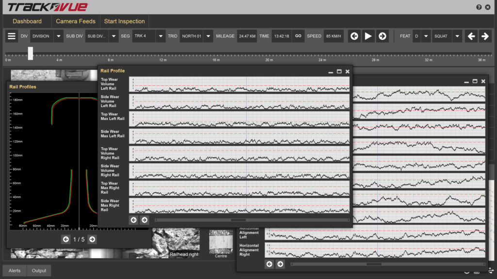
The following shows a picture of rail wear and geometry measurements as made by TrackVue Z series equipment in real-time on-board a train.
RV Advantage
- Track geometry measurements can be made in all track segments at full line speeds of 160 kmph every 20 cms along the direction of movement
- Vision, track geometry, rail wear and vehicle dynamics measurements are all made by a single equipment as a part of our patented technology
- Track geometry measurements are further correlated with rail-wheel interface measurements to confirm the degree to which poor track geometry is contributing to wheel and rail damage as opposed to issues cause by abnormal rail grinding